 RF
RFLDACS1 Physical Layer: Aircraft to Ground Communication
Advertisement
LDACS (L-Band Digital Aeronautical Communication System) is being developed as a data link for communication between Aircraft Stations and Ground Stations for air traffic control and maintenance.
EUROCONTROL has proposed two systems: LDACS1 and LDACS2. LDACS1 uses OFDM modulation and supports FDD (Frequency Division Duplexing). LDACS2 is based on GSM and supports TDD (Time Division Duplexing).
The transmission link from the Aircraft Station (AS) to the Ground Station (GS) is the “reverse link,” while the link from the Ground Station (GS) to the Aircraft Station is the “forward link.”
We will focus on the LDACS1 physical layer used in the Aircraft Transmitter and Ground Station receiver.
LDACS1 Physical Layer for Reverse Link
The LDACS1 physical layer for the reverse link is divided into a transmitter part (Aircraft Station) and a receiver part (Ground Station).
OFDM symbol in LDACS Reverse Link (Aircraft Transmitter)
| Specifications | Value |
|---|---|
| FFT Size | 64 |
| Number of Guard Carriers | 7 (Left), 6 (Right) |
| Number of Pilot Subcarriers | 12 |
| Number of DC carrier | 1 |
| Number of Used Data carriers | Total 50 (25 per user) |
| Subcarrier spacing | 9.765625KHz |
| Useful Symbol Time | 102.4 µS |
| Cyclic Prefix Time(11/64) | 17.6µS |
| Total OFDM symbol time | 120µS |
| Guard Time (Tg) | 4.8µS |
| Total FFT Bandwidth | 625KHz |
Three types of MAC sub-frames pass through the LDACS1 physical layer:
- Data segment
- Dedicated control segment
- Random Access Frame
The frame formation module varies based on these types, and pilot subcarrier values differ for each.
LDACS1 Transmitter Part (Aircraft)
Let’s analyze the processing of an RL Data PHY PDU through the LDACS1 physical layer, assuming the following modulation and coding parameters:
- Modulation Scheme: QPSK
- Coding Rate: 1/2
- RS parameter: (16,14,1)
- Total Coding rate: 0.44
- Number of uncoded bits: 112
- Number of coded bits: 268
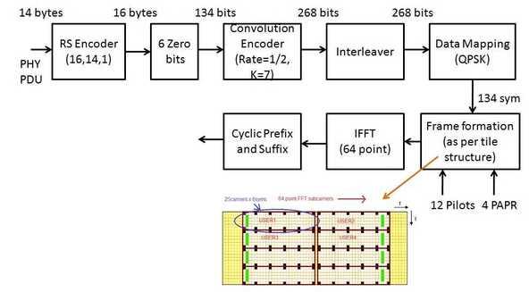
The steps involved in the LDACS1 physical layer transmitter chain are:
Step 1: A MAC sub-layer data, specifically a PHY PDU of 14 bytes, is input to the RS encoder, which outputs 16 bytes.
Step 2: Six zero tail bits are added to the 16 bytes, resulting in 134 bits.
Step 3: These 134 bits undergo zero tail biting convolution encoding at a rate of 1/2, producing encoded bits double the input size.
Step 4: Data is interleaved according to a provided permutation equation, producing 268 interleaved data bits.
Step 5: These 268 data bits are modulated using the QPSK symbol table, resulting in 134 QPSK data symbols.
Step 6: These data symbols are processed differently depending on the MAC sub-layer frame.
Frame formation for the Data segment is as follows: 12 pilots and 4 PAPR symbols are added. After removing the DC carrier, 12 pilots, and 4 PAPR symbols, we are left with 50 useful data carriers per FFT of size 64. For detailed LDACS1 frame structure refer LDACS1 frame structure .
A tile consists of 25 carriers and 6 symbols and is the minimum resource allocated to each user. One FFT can accommodate two users (USER#1 and USER#2). Remaining symbols are allocated to other users or the same users based on data bandwidth requirements.
Step 7: A 64-point IFFT is applied to this frame of data.
Step 8: A cyclic prefix and guard interval are added to the OFDM symbol samples from step 7.
LDACS1 Physical Layer Receiver (Ground Station)
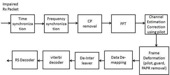
The following steps are performed by the LDACS1 physical layer receiver on received IQ data after it passes through the RF subsystems:
Step 1: Time and frequency offset estimation and correction are performed.
Step 2: The cyclic prefix and guard intervals are removed.
Step 3: A 64-point FFT is performed.
Step 4: The respective tile structure is segregated for the specific user. Channel estimation and correction are done based on the left or right pilot structure.
Step 5: Frame deformation occurs, removing pilots, guard intervals, and DC subcarriers from the received OFDM symbols.
Step 6: Data demapping (QPSK demapping) is performed, producing data bits.
Step 7: De-interleaving is applied to the demapped data.
Step 8: Viterbi decoding is applied to the de-interleaved data, correcting any errors in the received impaired data packet.
Step 9: Reed Solomon decoding (RS decoder) is applied to the data obtained in step 8.
Advertisement


