 RF
RF78xx and 79xx Voltage Regulator Circuits: Working and Operation
Advertisement
All voltage sources can’t provide a fixed output due to fluctuations in the circuit. To obtain a constant and steady output, voltage regulators are used. Integrated circuits (ICs) used for voltage regulation are called voltage regulator ICs. Here, we’ll discuss the 78xx and 79xx series of ICs.
78xx Voltage Regulator Circuit
The voltage regulator IC 7805 is a member of the 78xx series of voltage regulator ICs. It’s a fixed linear voltage regulator. The “xx” in 78xx represents the value of the fixed output voltage that the IC provides. For the 7805 IC, this is a +5V DC regulated power supply. This regulator IC also supports the addition of a heat sink. The input voltage can be up to 35V, and this IC can provide a constant 5V for any input voltage less than or equal to this threshold.
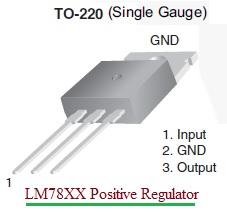
Here are the pin details of the 7805 IC:
- PIN 1 (INPUT): Should be in the range of 7V to 35V. An unregulated voltage is applied to this pin for regulation. Maximum efficiency is achieved at around 7.2V input.
- PIN 2 (GROUND): Connect the ground to this pin. It’s equally neutral (0V) for both input and output.
- PIN 3 (OUTPUT): A regulated output of +5V is available at this pin.
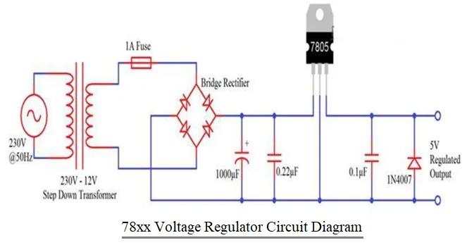
Figure 2 depicts a voltage regulator circuit diagram that produces regulated 5V from AC mains. The components used in this circuit are:
- 230V-12V Step-Down Transformer
- Bridge Rectifier (or 4 PN Diodes – 1N4007)
- 1A Fuse
- 1000µF Capacitor
- 7805 Voltage Regulator IC
- 0.22µF Capacitor
- 0.1µF Capacitor
- 1N4007 Diode
Let’s understand the working operation of the voltage regulator circuit based on the 7805 IC:
The AC power supply from the mains is first converted into an unregulated DC and then into a constant, regulated DC with the help of this circuit. The circuit consists of a transformer, a bridge rectifier (made from diodes), a linear voltage regulator (7805), and capacitors.
The circuit’s operation can be divided into two parts. In the first part, the AC Mains is converted into unregulated DC, and in the second part, this unregulated DC is converted into regulated 5V DC.
Initially, a 230V to 12V step-down transformer is used, and its primary winding is connected to the mains supply. The secondary winding is connected to a bridge rectifier (either a dedicated IC or a combination of 4 1N4007 diodes).
A 1A fuse is placed between the transformer and the bridge rectifier to limit the current drawn by the circuit to 1A. The rectified DC from the bridge rectifier is smoothed out using a 1000µF capacitor.
Therefore, the output across the 1000µF capacitor is an unregulated 12V DC. This is given as input to the 7805 Voltage Regulator IC. The 7805 IC then converts this to a regulated 5V DC, which can be obtained at its output terminals.
79xx Voltage Regulator Circuit
The 79xx series voltage regulators are negative voltage regulators, meaning they provide a stable and regulated negative output voltage.
One of the commonly used components from the 79xx series is the LM79xx IC, where “xx” denotes the specific output voltage, such as LM7912 for a -12V regulator.
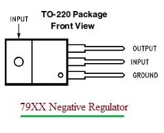
The pin details are as follows:
- Pin-1 (Input): This is the unregulated DC input voltage from an external power source. For the LM7912CT IC from Texas Instruments, the input voltage range is from -7V to -30V.
- Pin-2 (Ground): This is the common ground reference for the regulator circuit.
- Pin-3 (Output): This is the regulated DC output voltage. The voltage level is determined by the specific part number. For the LM7912, the output voltage is -12V.
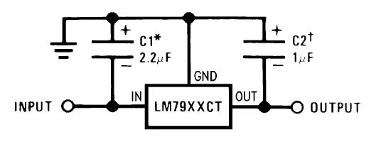
Let’s understand the working operation of a voltage regulator circuit based on the 7912 IC:
Similar to the 78xx series, the LM79xx series voltage regulators have an internal reference voltage. This reference voltage is typically set at the desired negative output voltage (e.g., -12V for the LM7912).
The internal circuitry compares the reference voltage with a fraction of the output voltage through a feedback loop. If the output voltage tends to rise above the desired level, the regulator takes corrective action to reduce it.
The IC includes a control element, often a pass transistor, that regulates the flow of current from the input to the output based on the feedback mechanism. This control element adjusts itself to maintain a stable negative output voltage.
The feedback loop continuously monitors and adjusts the output voltage to compensate for variations in input voltage and load conditions.
Voltage regulators may generate some heat during the regulation process. To dissipate this heat, heat sinks are often used, especially when dealing with higher voltage differentials or larger currents.
Conclusion
In summary, the 78xx series provides positive voltage regulation, ensuring a constant positive output voltage, while the 79xx series provides negative voltage regulation, delivering a stable negative output voltage. Both series operate on similar principles, utilizing an internal reference voltage, feedback loops, and control elements to adjust the current flow and maintain a consistent output voltage despite variations in input voltage or load conditions.
Advertisement


