 RF
RFCrystal Detector Basics and Circuit Explained
Advertisement
This page describes the basics of crystal detectors, including the crystal detector circuit, characteristics, and mathematical equations. Crystal detectors are widely used in RF and microwave fields due to their sensitivity and simple design.
Applications of Crystal Detectors:
- Used as a video detector, which produces a DC output based on the input signal frequency (unmodulated or modulated).
- Used in RF mixers for super heterodyne circuits.
The semiconductor chip and metal whisker are two essential parts of a crystal detector. Microwave crystal detectors typically use a silicon chip (1/16 inch square) and a tungsten whisker wire (3/1000 inch diameter). Other parts are required to support the chip & whisker and to couple electric energy to the detector.
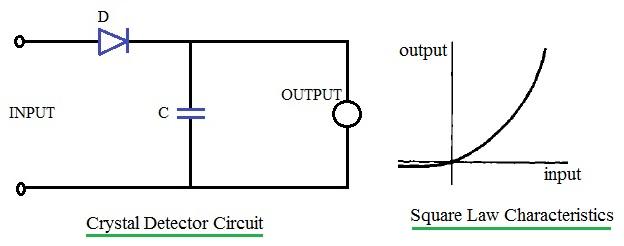
Crystal detectors are useful at microwave frequencies due to their smaller size. This small size, however, limits the power handling capability of the crystal detector to about 100 mWatt. Figure 1 (see image above) depicts a crystal detector circuit along with its characteristics.
Crystal Detector Characteristics
The detector’s characteristic curve is square law in nature; hence, the output voltage is proportional to the square of the input voltage. This relationship is explained mathematically in the section below.
The curve demonstrates that a large variation in output voltage results in a minor variation in input voltage. This indicates the high sensitivity of the crystal detector. This curve can be approximated by a Taylor series, as shown in Equation 1:
i = a0 + a1*v + a2*v^2 + a3*v^3 ...Equation-1
Let’s define the input voltage v as:
v = A*cos(w*t) ...Equation-2
Where:
A= Amplitudew= 2πf (angular frequency)
Substituting Equation 2 into Equation 1, we get:
i = a1*(A*cos(w*t)) + a2*(A*cos(w*t))^2 + a3*(A*cos(w*t))^3 ... Equation-3
For extremely small signals, all terms except the first one are negligible. This simplifies the equation to:
i = a1*(A*cos(w*t))
Hence, the current is proportional to the applied voltage. In this case, the crystal behaves as a simple resistor with a negligible amount of DC current flowing through the milliampere meter.
For larger signals, the second term must be included in the equation, leading to:
i = a1*(A*cos(w*t)) + a2*(A*cos(w*t))^2 = a1*(A*cos(w*t)) + a2* (A^2 /2) *(1+cos(2*w*t)) ... Equation-4
From this equation:
- The current includes a DC component,
a2*A^2 /2, which flows through the mA meter. - The second component,
a2* (A^2 /2)*cos(2*t), flows through the capacitor (C). - Therefore, the milliampere meter indicates a reading that is proportional to the square of the amplitude
Aof the microwave voltage.
Advertisement


