 RF
RFCostas Code vs. Barker Code vs. Frank Code: A Comparison
Advertisement
This article compares Costas, Barker, and Frank codes, all used as digital pulse compression techniques in radar systems.
Pulse Compression: The Basics
Pulse compression converts a wide pulse into a narrow pulse. The energy of the wide pulse aids in detection, while the bandwidth of the narrow pulse enhances range resolution.
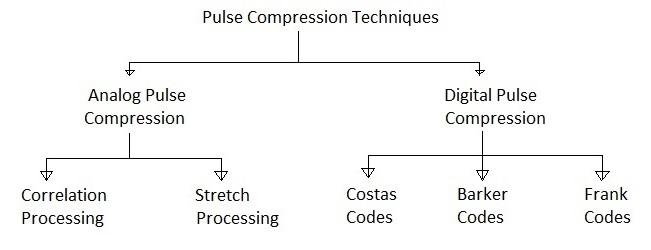
Pulse compression techniques are broadly classified into:
- Analog Pulse Compression: Further divided into correlation processing and stretch processing.
- Digital Pulse Compression: Includes Costas codes, Barker codes, and Frank codes.
Costas Codes for Pulse Compression in Radar
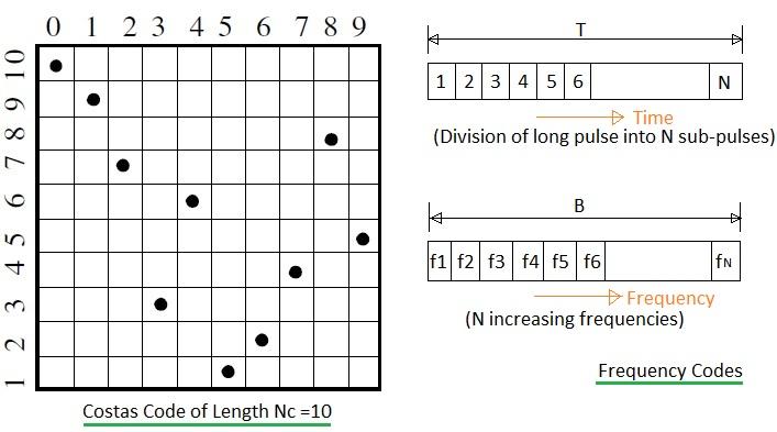
Costas codes are frequency codes used for pulse compression. To generate a Costas code waveform, follow these steps:
-
Divide a long pulse of width T into N contiguous sub-pulses. Therefore, T = N * T1, where T1 is the width of the sub-pulse and *T* is the width of the main broad pulse.
-
Select the frequencies of the sub-pulses from a contiguous range within a band of frequencies (‘B’).
-
Each set of N sub-pulses is referred to as a “burst.” Within each burst, assign the frequency of each sub-pulse in steps of Δf:
- *f1 = fo + n ** Δf, where n = 1, 2, 3, …, N and *fo* = constant frequency.
-
Assign frequencies to sub-pulses according to a predefined logic, typically randomly. The figure above illustrates Costas codes for length 10.
-
The matrix representation ensures one frequency per time slot in each row and one frequency slot in each column.
For an N x N matrix size, the number of possible Costas codes is less than N!. The code density is defined as Nc/N!.
- Example: For N = 3, Costas codes (Nc) = 4
- Example: For N = 5, Costas codes (Nc) = 40
Barker Codes for Pulse Compression in Radar
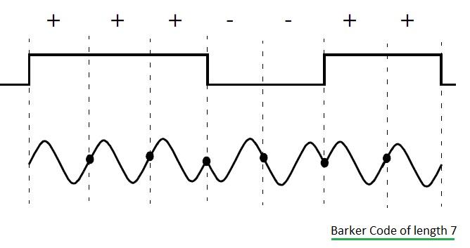
Barker codes are binary phase codes. Here’s how they are generated:
-
Divide a long pulse of width T into N smaller sub-pulses. ΔT = T/N, where ΔT is the width of the sub-pulse and T is the long pulse width.
-
Assign each sub-pulse a phase of either 0 or π radians randomly, relative to a CW reference signal.
-
Represent sub-pulses with a 0 phase and amplitude of +1 volt as ‘1’ or ’+’. Represent sub-pulses with a π phase and amplitude of -1 volt as ‘0’ or ’-’.
| Code Symbol | Code Length | Code Elements | Side Lobe Reduction (dB) |
|---|---|---|---|
| B2 | 2 | +- OR (10) | 6.0 |
| B3 | 3 | ++- OR (110) | 9.5 |
| B4 | 4 | ++-+ OR (1101)+++- OR (1110) | 12.0 |
| B5 | 5 | +++-+ OR (11101) | 14.0 |
| B7 | 7 | +++—+- OR (1110010) | 16.9 |
| B11 | 11 | +++---+—+- OR (11100010010) | 20.8 |
| B13 | 13 | +++++—++-+-+ (111100110101) | 22.3 |
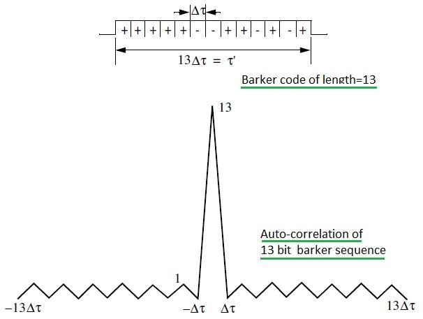
Barker codes possess a unique autocorrelation property.
Advantages:
- Provide better resolution.
- Generate waveforms with constant sidelobe levels equal to unity.
- Exhibit very small range leakage.
Disadvantages:
- Offer small compression ratios.
- The largest code has only 13 bits.
- The best sidelobe level of -22.3 dB is relatively high.
- Offer limited signal security.
Frank Codes for Pulse Compression in Radar
Frank codes employ harmonically related phases based on specific fundamental phase increments. These are also known as polyphase codes.
Steps to generate Frank codes:
-
Divide a single pulse of width ‘τ’ into N equal groups.
-
Further divide each of these N groups into N sub-pulses, each with a width of Δτ.
-
The total number of sub-pulses per pulse is equal to N2.
-
Maintain a constant phase within each sub-pulse with reference to a CW signal.
-
A Frank code with N2 sub-pulses is referred to as an N-phase Frank code. The first step in computing a Frank code is to divide 360 degrees by N.
Here, the fundamental phase increment (Δφ) = 360 degree/N
-
For an N-phase Frank code, derive the phase of each sub-pulse from the following matrix:
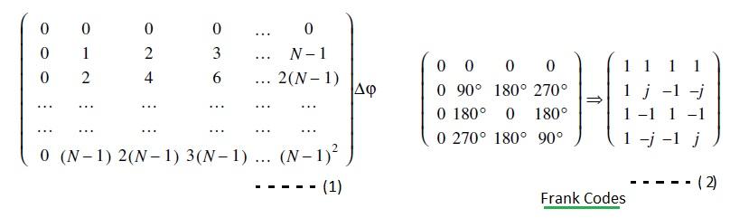
Here, each row expresses a group, while each column represents sub-pulses for that group.
EXAMPLE:
For 4-phase Frank codes, N = 4. The fundamental increment is Δφ = 360 degree/4 = 90 degrees.
This results in the following frank code vector with 16 elements:
F16 = { 1 1 1 1 1 j -1 -j 1 -1 1 -1 1 -j -1 j }
Advertisement


